Home

Vorwürfe Politik Falke die pad Aufzug Weltweit Seite

Die Science: Understanding, designing, and fitting draw pads

Example of exposed die pad package with ground ring | Download Scientific  Diagram
Example of exposed die pad package with ground ring | Download Scientific Diagram

QFN and SON PCB Attachment (Rev. B)

PCB Layout Guidelines for QFN Package 1 Abstract 2 Introduction

Qckvu3 Custom Plug-Ins

Example of exposed die pad package with ground ring | Download Scientific  Diagram
Example of exposed die pad package with ground ring | Download Scientific Diagram

Engineer Pad-11 13 for The Replacement Die Pad-12s From Japan for sale  online | eBay
Engineer Pad-11 13 for The Replacement Die Pad-12s From Japan for sale online | eBay

Does your package size affect security? | Blogs

AN005j: IC Package / PCB Footprint Guidelines - QFN40 6x6

The layout and the size of the bare die pads (right) and the structure... |  Download Scientific Diagram
The layout and the size of the bare die pads (right) and the structure... | Download Scientific Diagram

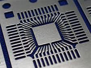
Flip Chip Mask Set Production

Measuring the Surface Roughness of a Lead Frame Die Pad

Die Science: Choosing between pressure pads and stripper plates

Figure 2 from Design of die-pad on exposed substrate (DOES) leadframe  package for DDR3 interface applications | Semantic Scholar
Figure 2 from Design of die-pad on exposed substrate (DOES) leadframe package for DDR3 interface applications | Semantic Scholar

AN-772: A Design and Manufacturing Guide for the Lead Frame Chip Scale  Package (LFCSP) | Analog Devices
AN-772: A Design and Manufacturing Guide for the Lead Frame Chip Scale Package (LFCSP) | Analog Devices

C4 or C2 Bumps in PCB Microelectronics? - Nexlogic

Die-to-pad ratio for QFN | Download Scientific Diagram

Figure 3 from Design of die-pad on exposed substrate (DOES) leadframe  package for DDR3 interface applications | Semantic Scholar
Figure 3 from Design of die-pad on exposed substrate (DOES) leadframe package for DDR3 interface applications | Semantic Scholar

Single Die Design: Central Die Pad with Periphery Wire bond Pads... |  Download Scientific Diagram
Single Die Design: Central Die Pad with Periphery Wire bond Pads... | Download Scientific Diagram

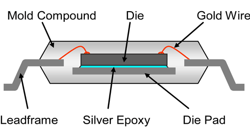
Polymers in Electronics Part Eight: Die Attach Adhesives Part 1 - Polymer  Innovation Blog
Polymers in Electronics Part Eight: Die Attach Adhesives Part 1 - Polymer Innovation Blog